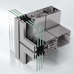
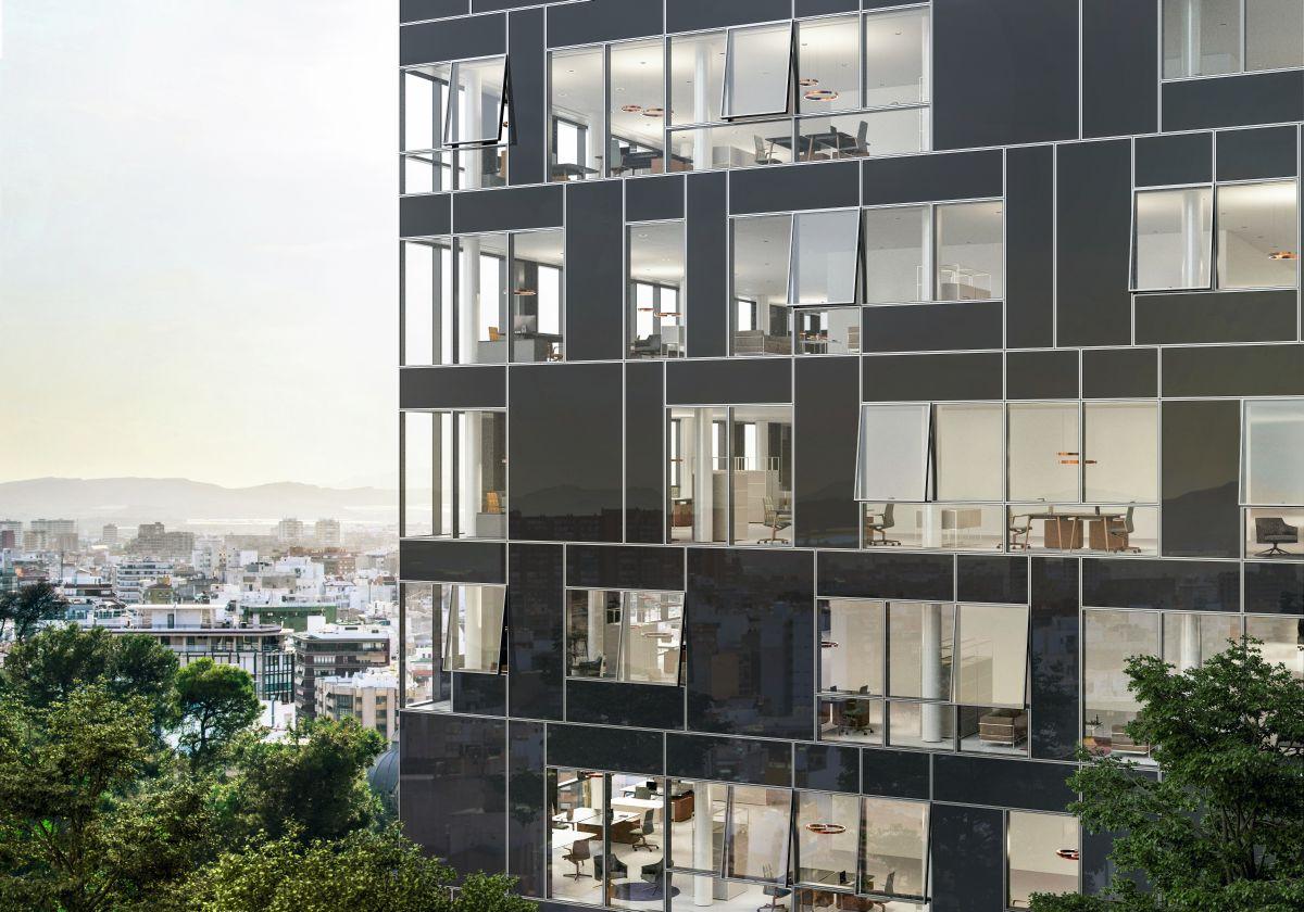
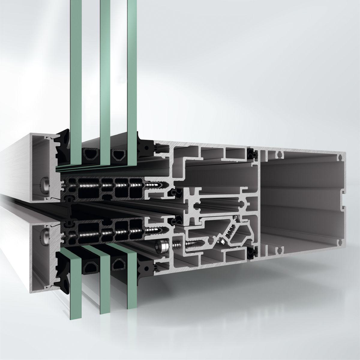
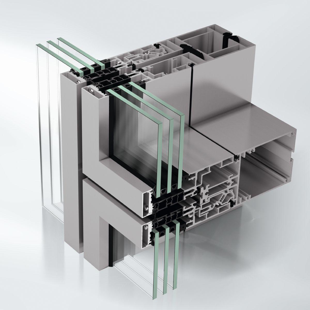
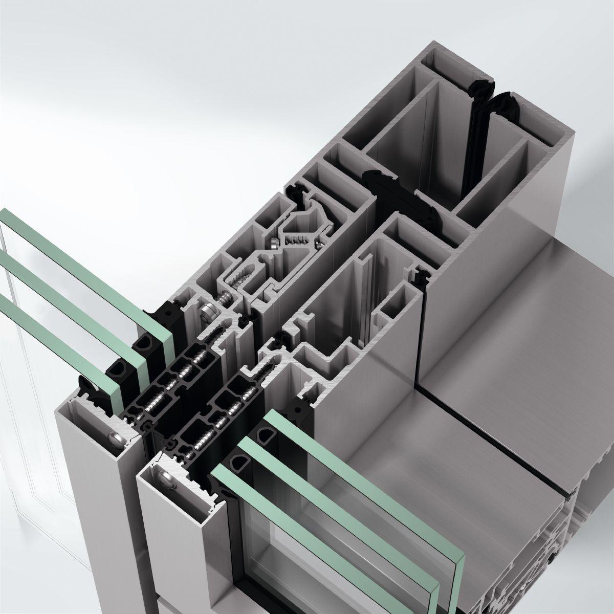
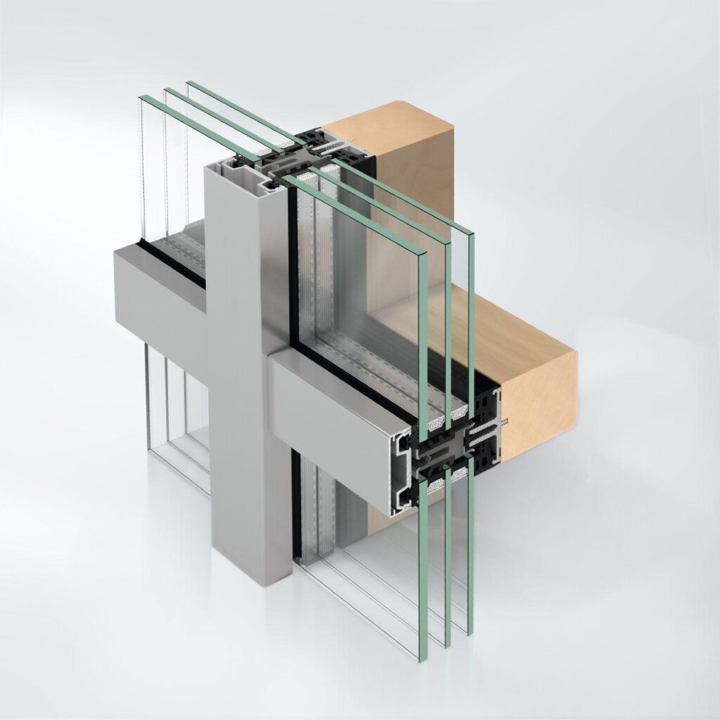
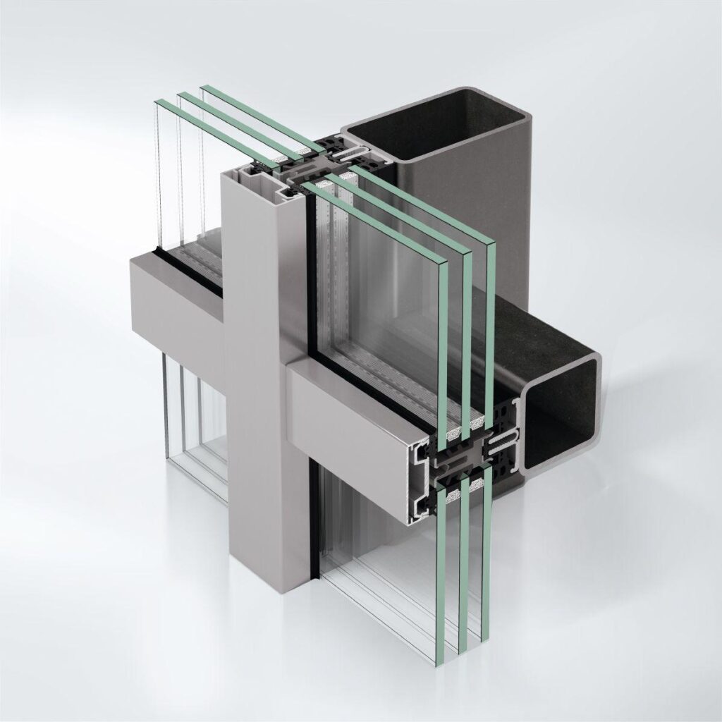
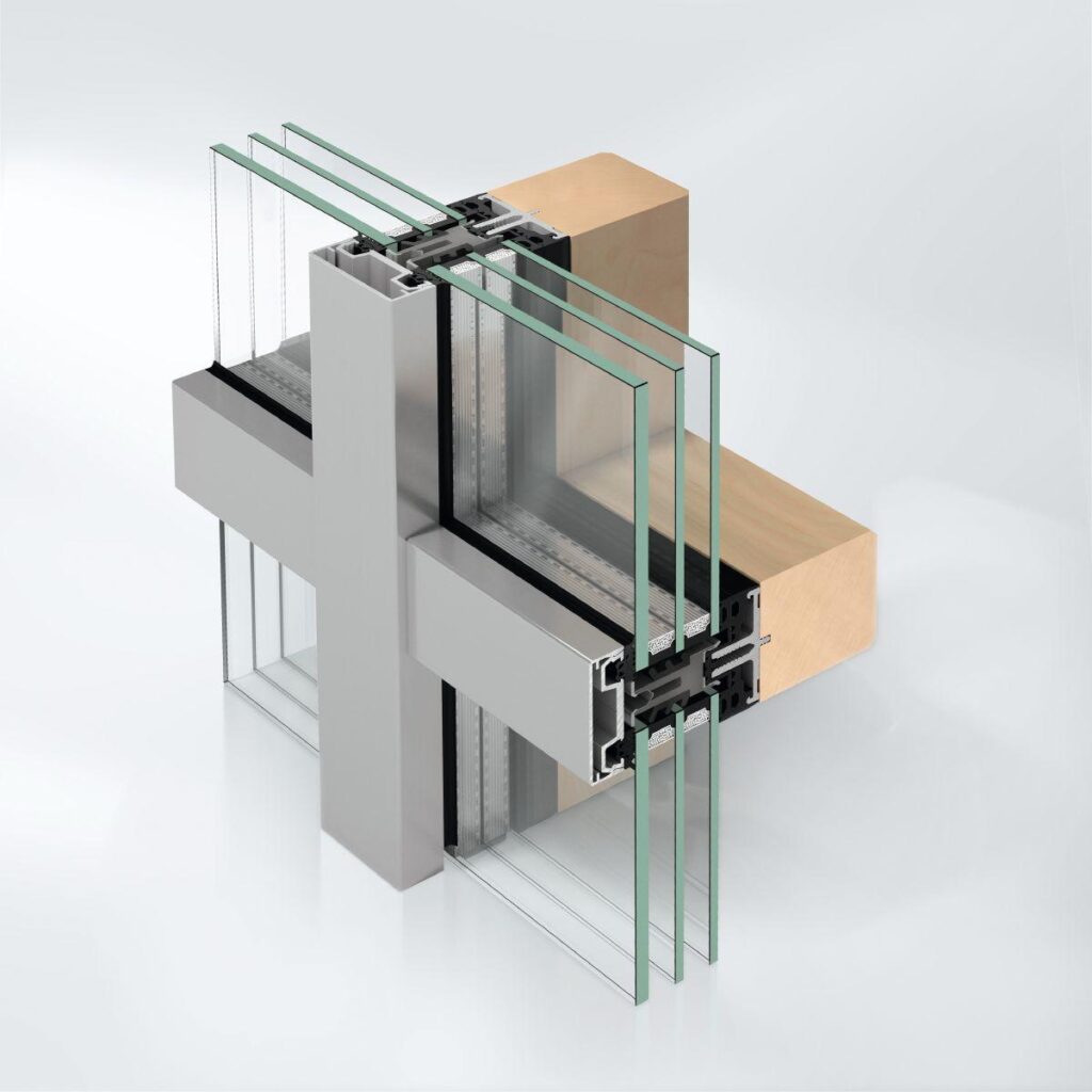
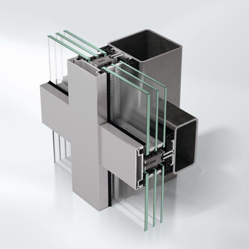
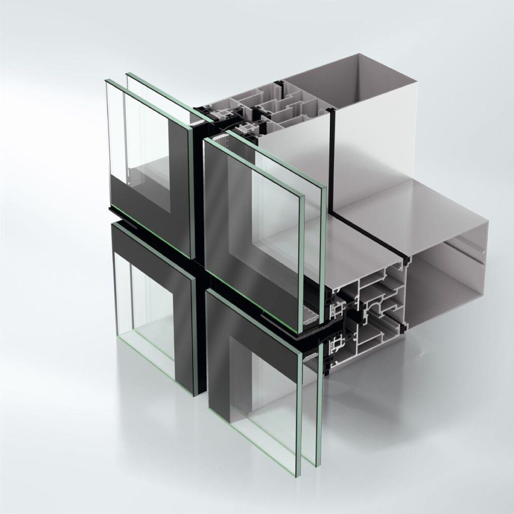
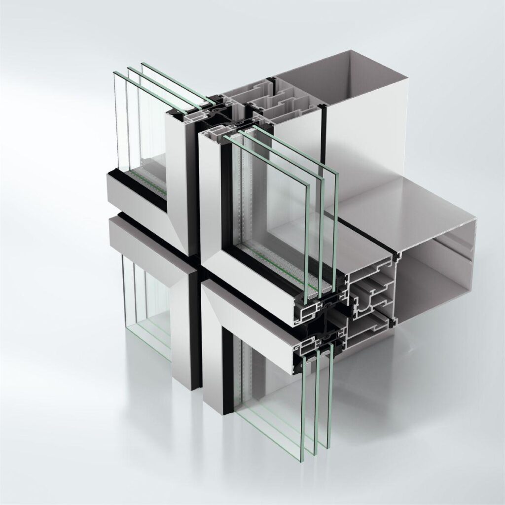
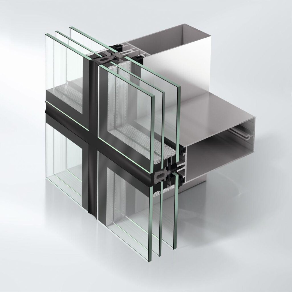
Schüco AF UDC 80 CV thermally insulated self-supporting aluminium façade system, with concealed integrated opening units (part of the AF UDC 80 façade system platform)
As unitised façade for multi-storey façades with room-side load-bearing structure with 80 mm face width
Construction features (façade supporting structure):
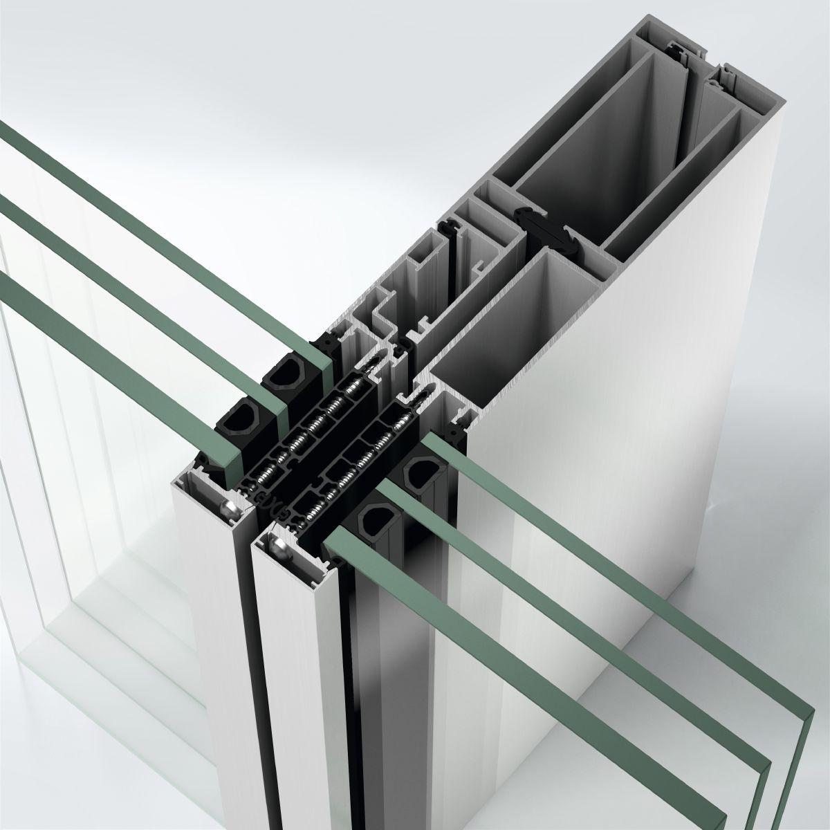
The supporting structure of the façade construction consists of multi-chamber hollow profiles in element construction, mitred by means of corner connectors with SCHÜCO injection moulding and bonding technology, optionally with glazing bars (at least one glazing bar for the opening element) inserted by means of T-connectors and sealing pieces with integrated sealing channels for sealing the H-joints.
The glazing bars can be arranged horizontally and vertically and have an inner and outer face width of 80 mm, 85 mm or 107 mm (depending on the expansion stage).
All profile edges are rounded. Sizes max. 3000 x 4000 mm, element weight up to max. 1000 kg (fixed panels up to max. 450 kg, opening elements up to max. 160 kg).
Different glass supports are used for a cost-efficient design. The glass support load level I is designed for up to 300 kg and the glass support load level II for up to 500 kg.
Construction features (insert elements):
The concealed insert elements (opening elements and fixed panels) consist of insert frames, mitred using corner connectors with SCHÜCO injection moulding and adhesive technology.
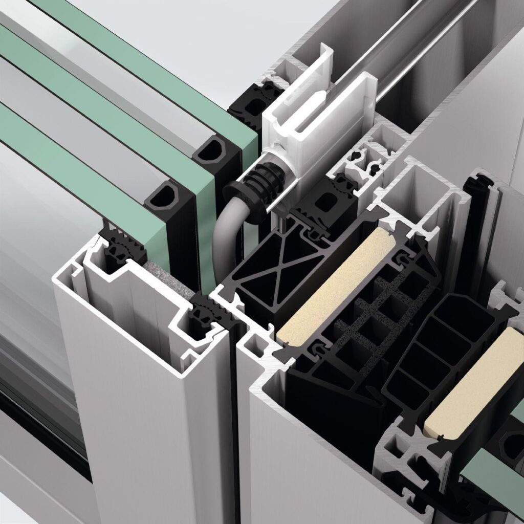
A special design feature is the pressure-resistant multi-chamber insulators, which are inserted and screwed into the screw channel of the insert frame.
By using different insulator variants (without foam, with foam in the glazing rebate area), Uf values of 1.25 W/m²K are achieved in combination with the glazing.
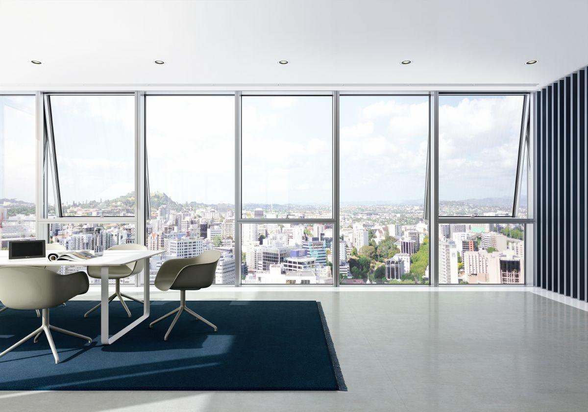
Opening elements can be realised with manual fittings as bottom-hung or parallel opening windows. In the joint area between the multi-chamber hollow profiles of the supporting structure and the insert frames, there is a filigree shadow gap of only 3 mm.
Construction features (glazing):
The use of insulating glass with glass thicknesses of 22 to 70 mm is possible; single glazing with glass thicknesses of 6 mm to 12 mm can also be used in the cold parapet area.
The insulating glass is mechanically fixed by means of circumferentially mitred pressure profiles and cover shells. On the room side, the panes are fixed by means of glass contact seals made of EPDM and on the outside by means of a plug-in keder seal to compensate for glass tolerances. All glass panes, including those of the insert elements, are arranged in the same plane.
Design feature (opaque surfaces):
For easy installation of flush or projecting opaque surfaces, defined and statically calculated transfer points are available through a system connection. The load is transferred via a statically defined rung into which bolts are screwed. By means of the combination of rung and bolt, the maximum forces to be absorbed can be specified, which the substructure may transfer into the system.
Coupling of the elements:
The horizontal element coupling is carried out by means of flexible saddle gaskets and coupling gaskets made of EPDM, which are to be inserted into the gasket receiving grooves. The vertical element coupling is carried out by means of façade crossbars in the case of elements arranged one above the other or by means of coupling pieces in the case of elements arranged offset. The coupling joints of the seals are to be overlapped, the vertical coupling seals overlap the horizontal saddle seals, here it is possible to work with a minimum use of liquid sealant due to special sealing pieces. An EPDM seal, completely pre-assembled in the workshop, a surface-treated aluminium clip profile or a horizontally continuous EPDM seal can be inserted into the seal receiving groove on the room side. A continuous saddle seal is to be fitted horizontally at the bottom in the outer seal mounting grooves when installing the elements. The saddle seal is put over a support profile so that the elements can be arranged on top of each other in a process-safe manner and a high driving rain tightness of 1650 Pa is achieved.
Field by field, the elements receive a tolerance-compensating EPDM pre-chamber seal on the outside, processed as a sealing frame or as yard goods with sealing corners. This seal is to be drawn into the groove in the insulator. The outer cover shell is fixed by clipping it onto the pressure profile; flushness in the mitre corners is achieved by a mitre plate on the pressure profiles. The inner frame profiles as well as the surrounding outer cover shells are given a surface treatment as described in more detail in the section on surface treatment.
The horizontal butt joint (= vertical dimension between two superimposed façade elements) has a joint dimension of 10 mm or 15 mm and can accommodate tolerances of ± 2.5, ± 5 mm or ± 10 mm depending on the construction method, e.g. due to ceiling movements.
Design feature (combinatorics UDC 80 with UDC 80CV):
For a seamless combination between the Schüco AF UDC 80 and Schüco AF UDC 80 CV systems, the supporting structures of the individual systems are matched to each other and can be easily connected using the existing seals and system components.