Large louvre blades in a special format for individual façade designs
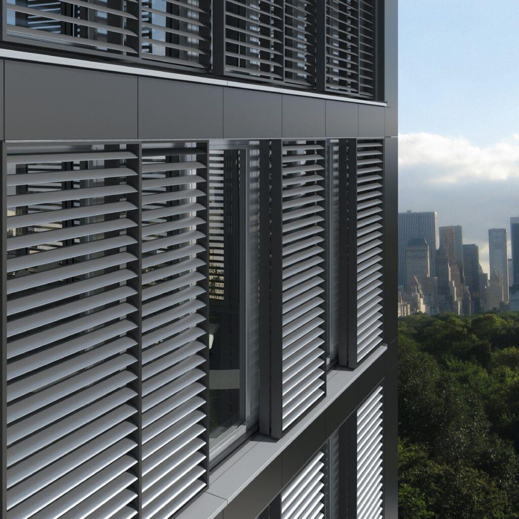
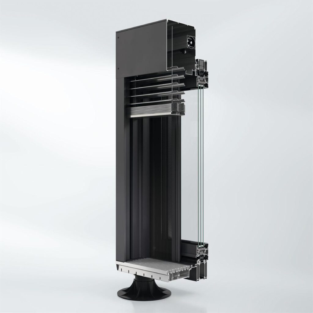
Whether installed horizontally or cantilevered, the Schüco ALB (Aluminium Louvre Blades) sun shading system with C or Z-shaped large louvre blades makes it possible to easily plan and construct large-scale, individual sun shading and weather protection solutions.
The wind-resistant system offers architects, specifiers and fabricators attractive aesthetic and functional advantages, guaranteeing the highest degree of quality, security and flexibility.
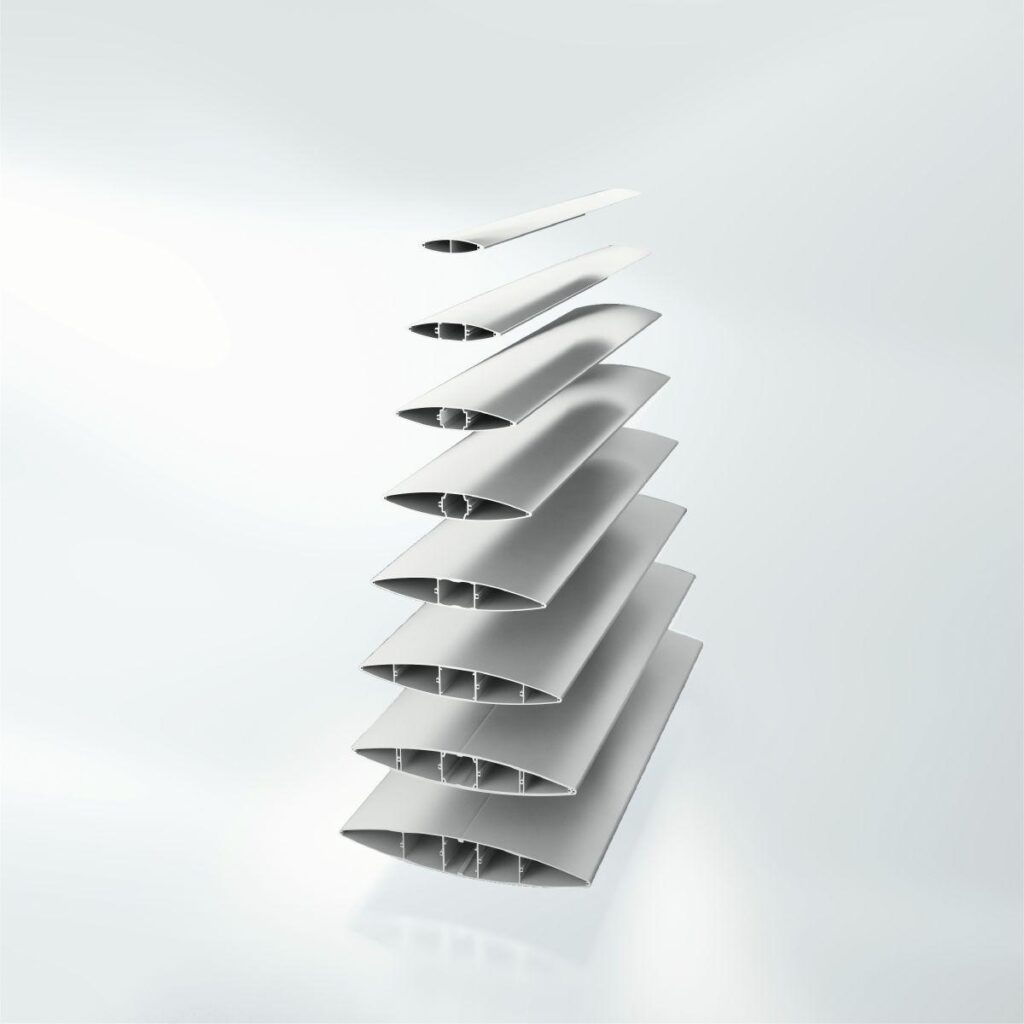
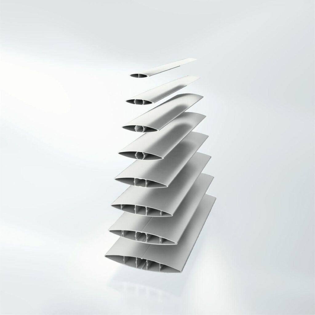
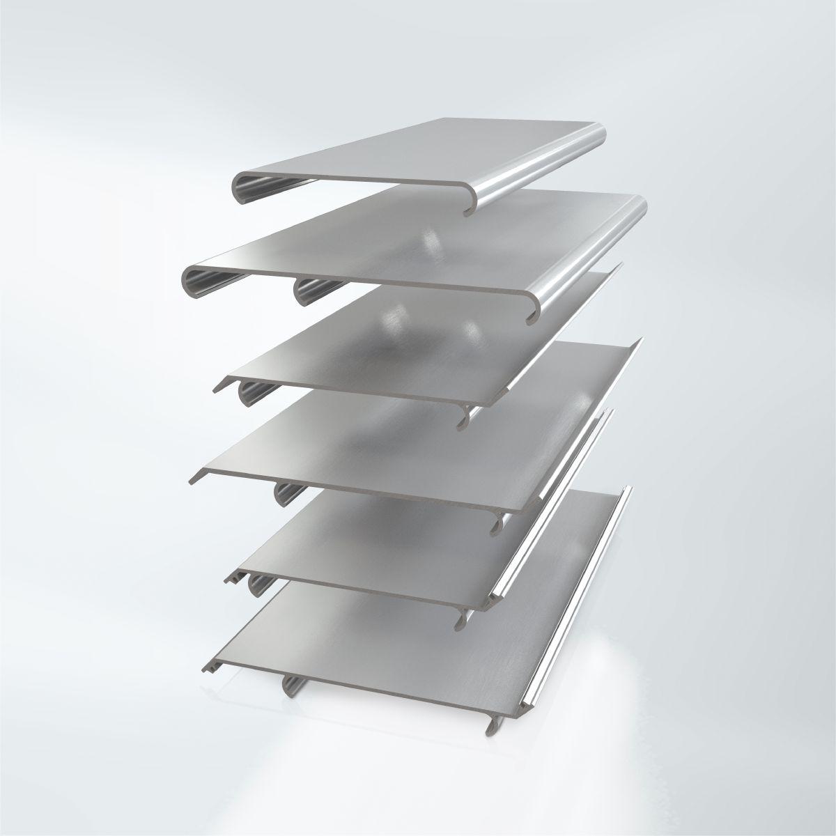
This includes a large selection of louvre blades with a wealth of geometries and widths. The distances between the louvre blades can be easily modified and thus adapted to the locally prevailing position of the sun. This means that, in addition to weather protection, thermal loads can also be significantly reduced.
The high degree of prefabrication and the convenient “stacking” installation system of the C and Z-shaped large louvre blades at the building site ensure reliable and fast installation.
Schüco C and Z-Shaped Louvre Blades ALB
as sun shading and weather protection with many variations for large-scale, individual façade designs.
With passive, horizontally / cantilevered, corrosion-resistant louvre blades made from extruded aluminium profiles.
The regulations and requirements of the local building authority must be observed in all designs.
Design features
The louvre blade system consists of passive, corrosion-resistant extruded aluminium profiles.
They can be used as either horizontal or cantilevered sun shading units.
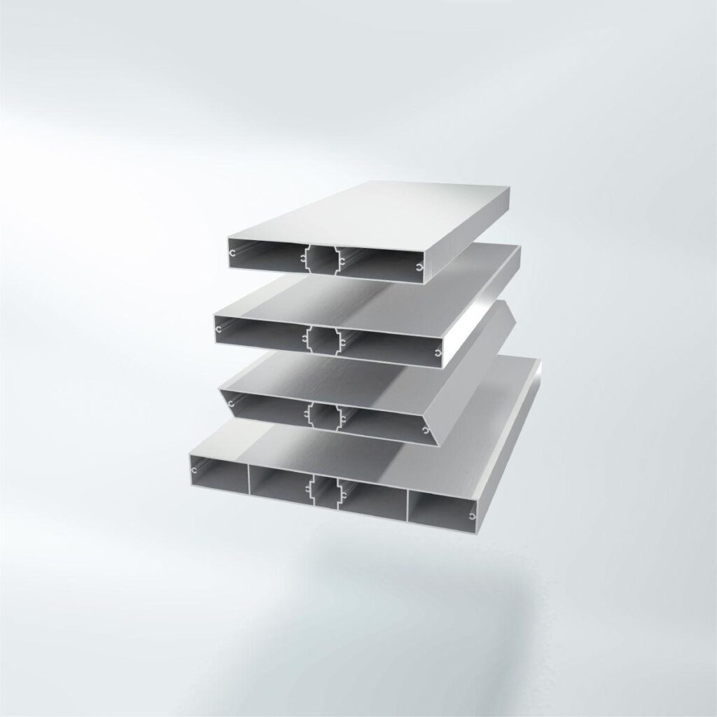
A wide range of louvre blade geometries is available:
C 100, C 150, Z 100, Z 120, Z 100 VS and Z 120 VS.
System solutions with bird guard and flyscreen are available depending on the application.
Louvre blade fixings
The mounting rail is attached to the wall, façade or a bracket.
The lowest bracket or the bracket that is inserted first must always be secured with screws. Further screws must be fixed to at least every tenth bracket as well as the top bracket/the bracket inserted last.
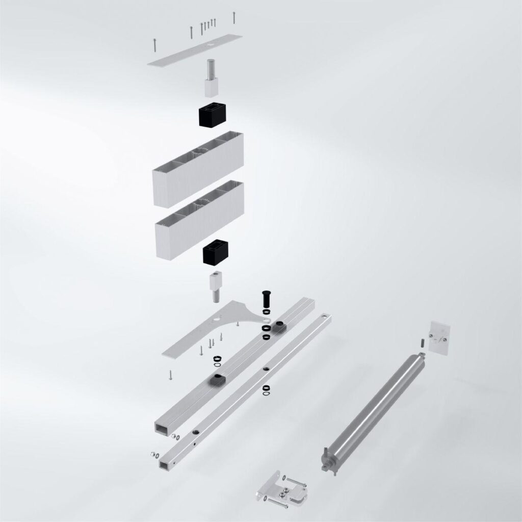
The clamp fixing brackets are stacked in the mounting rail, alternating with the spacer profiles.
The spacer profiles are cut on a project-specific basis to a length which is calculated from the critical angle of the sun elevation, for example, or a fixed distance.
The louvre blades are then installed on the brackets by means of clip-on technology.
The stacking installation principle is used in both the horizontal, façade-mounted system design and the cantilevered system design.
Louvre blade angle
The angle of the louvre blades is dictated by the shape and the application (façade-mounted or cantilevered) of the clamp fixing brackets (either 30°, 45° or 60°). The corner construction or suspended design is enabled by rotatable clamp fixing brackets (45°), amongst other things.
Material
The aluminium profiles consist of EN AW 6060 T66.
The clamp fixing brackets consist of PA 6 GF15 or GF30 plastic
Connecting units must be designed in A2 / A4 (for use in atmospheres containing salt, e.g. near the coast).
Surfaces
The louvre blades are available anodised, wet-painted or powder-coated in accordance with the Schüco system finish.
Please adjust the following design options to suit the application:
Sun shading, cantilevered, intermediate, on existing substructure
The mounting rail is fixed from the top/bottom to an existing cantilevered bracket construction.
Either the asymmetrical or symmetrical mounting rail is fixed to the existing bracket in accordance with the requirements. The rails must be fixed to the existing bracket construction by means of fixing units.
Depending on the application (fixed/suspended) the corresponding clamp fixing brackets and spacer profile are inserted alternately in the predefined locating groove of the mounting rail by means of stacking.
The module width (distance between the brackets) must be planned in accordance with the structural requirements on a project-specific basis.
However, each louvre blade must be held by at least three clamp fixing bracket legs.
All connecting units must be designed in A2 / A4 (for use in atmospheres containing salt, e.g. near the coast).
Sun shading, cantilevered, surface-mounted connection to existing substructure
The pilaster profile is fixed from the top/bottom to an existing cantilevered bracket construction.
The pilaster profiles must be fixed to the existing bracket construction by means of fixing units.
Depending on the application (fixed/suspended) the corresponding clamp fixing brackets and spacer profile are inserted alternately in the predefined locating groove of the pilaster profile by means of stacking.
The module width (distance between the brackets) must be planned in accordance with the structural requirements on a project-specific basis.
However, each louvre blade must be held by at least three clamp fixing bracket legs.
All connecting units must be designed in A2 / A4 (for use in atmospheres containing salt, e.g. near the coast).
Sun shading, cantilevered, surface-mounted connection to existing façade construction
Each slide-on profile is connected to the bracket attachment/an existing cantilevered bracket construction such that it is compatible with the system.
The bracket attachment/existing bracket construction transfers the forces to the mullion/transom construction by means of the fixing technology.
Clamp fixing brackets and the spacer profile are inserted alternately in the predefined locating groove of the pilaster profile by means of stacking.
The module with (distance between the pilaster profiles) must be planned in accordance with the structural requirements on a project-specific basis.
However, each louvre blade must be held by at least three clamp fixing bracket legs.
All connecting units must be designed in A2 / A4 (for use in atmospheres containing salt, e.g. near the coast).
Sun shading, façade-mounted on an existing substructure
The U-shaped retaining profile is fixed to the substructure/wall.
Clamp fixing brackets and the spacer profile are inserted alternately in the predefined locating groove by means of stacking.
The module width (distance between the retaining profiles) must be planned in accordance with the structural requirements on a project-specific basis.
However, each louvre blade must be held by at least three clamp fixing brackets.
Option A:
Bracket is screwed onto the profile (M4 thread) or through the profile onto the building structure (clearance hole M4).
Option B:
Bracket is clamped to the profile.
The lowest bracket of each pilaster must be screwed in place (as per option A).
Further fixings must be made for at least every tenth bracket and the top bracket in accordance with option B.
All connecting units must be designed in A2 / A4 (for use in atmospheres containing salt, e.g. near the coast).
Sun shading, façade-mounted on existing façade construction
The pilaster profile is connected to the bracket attachment via the adapter profile such that it is compatible with the system.
The bracket attachment transfers the forces to the mullion/transom construction by means of the fixing technology.
Clamp fixing brackets and the spacer profile are inserted alternately in the predefined locating groove.
The module width (distance between the retaining profiles) must be planned in accordance with the structural requirements on a project-specific basis.
However, each louvre blade must be held by at least three clamp fixing brackets.
The louvre blades are installed by means of stacking.
Option A:
Bracket is screwed onto the profile (M4 thread) or through the profile onto the building structure (clearance hole M4).
Option B:
Bracket is clamped to the profile.
The lowest bracket of each pilaster must be screwed in place (as per option A).
Further fixings must be made for at least every tenth bracket and the top bracket in accordance with option B.
All connecting units must be designed in A2 / A4 (for use in atmospheres containing salt, e.g. near the coast).
Addition:
A mesh must additionally be fixed for the design with flyscreen.
The mesh is fixed behind the louvre-blade construction (U-shaped retaining profile) by means of an additionally mounted flyscreen strip.
The mesh is positioned and fixed to the flyscreen strip by means of a round gasket.
The special Z-shaped louvre blade profiles (Z 100 VS and Z120 VS) are used for the bird guard design.
The bird guard sheet metal to be inserted in the Z-shaped louvre blades must be fabricated or ordered by the metal fabricator on a project-specific basis.
Tell us what you need and we’ll get back to you with a custom offer.
Përshkruani shkurt projektin tuaj. Do t’ju kontaktojmë së shpejti.