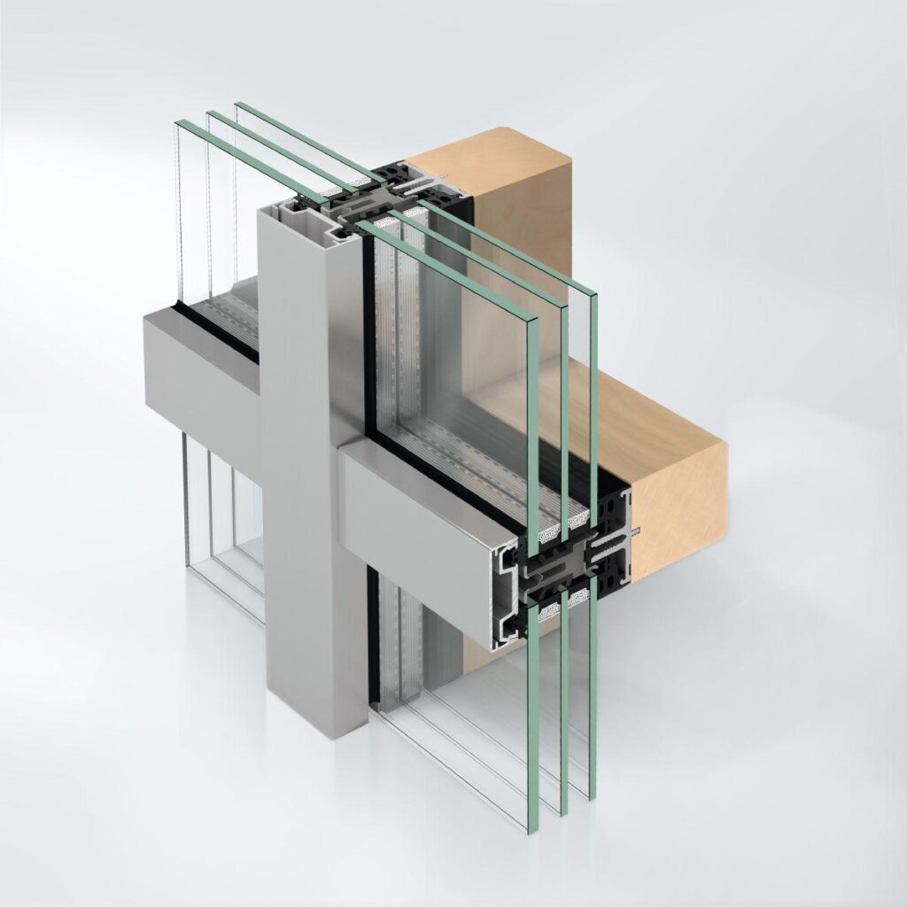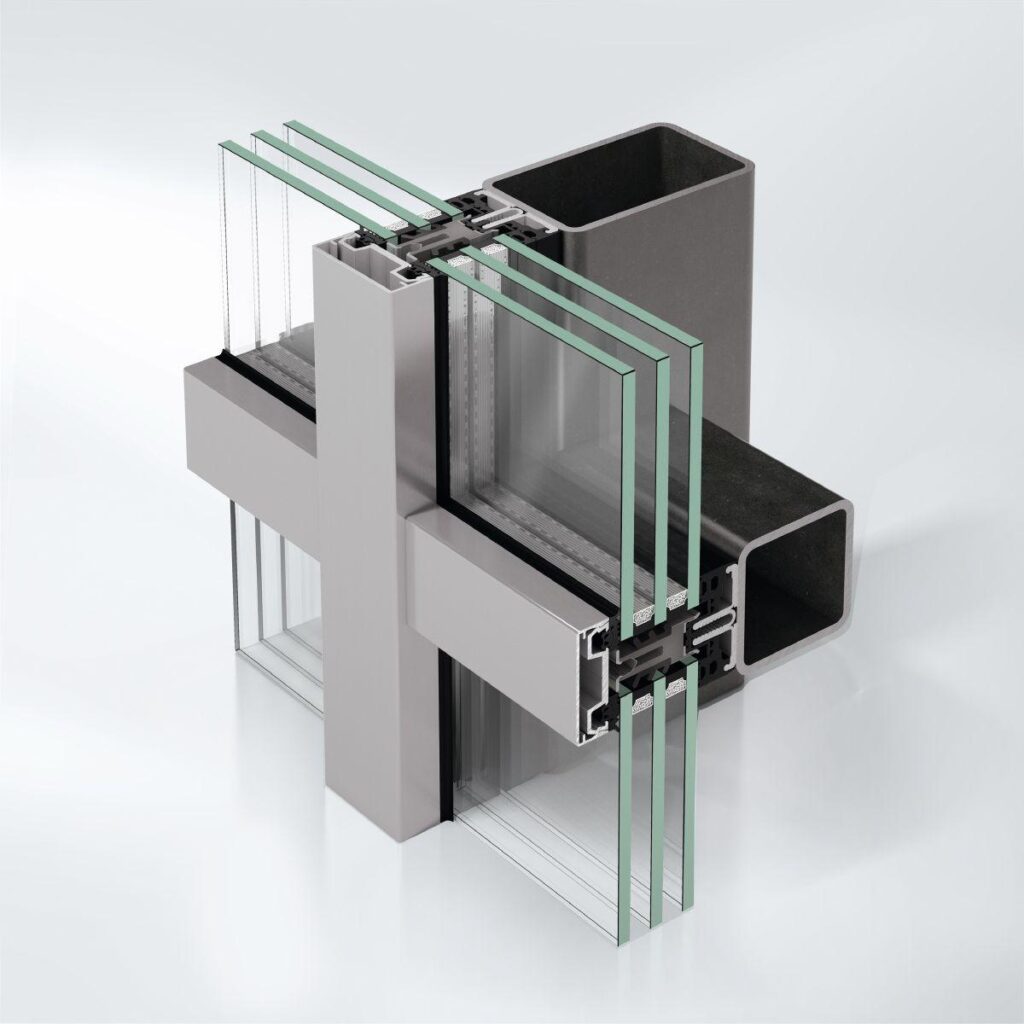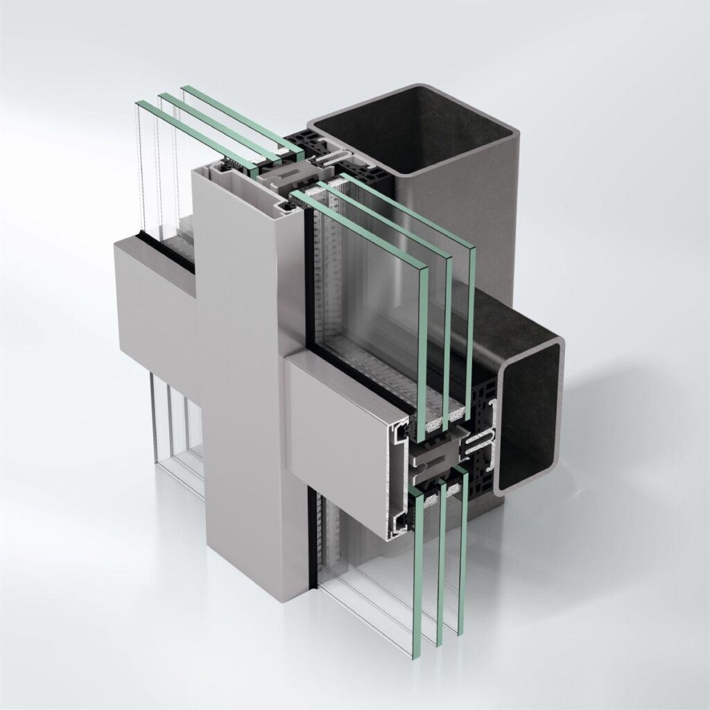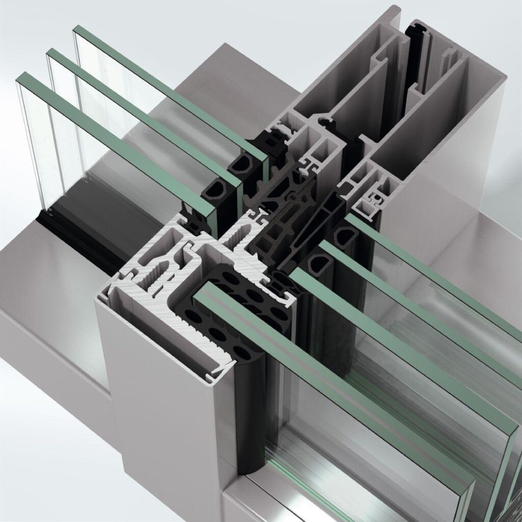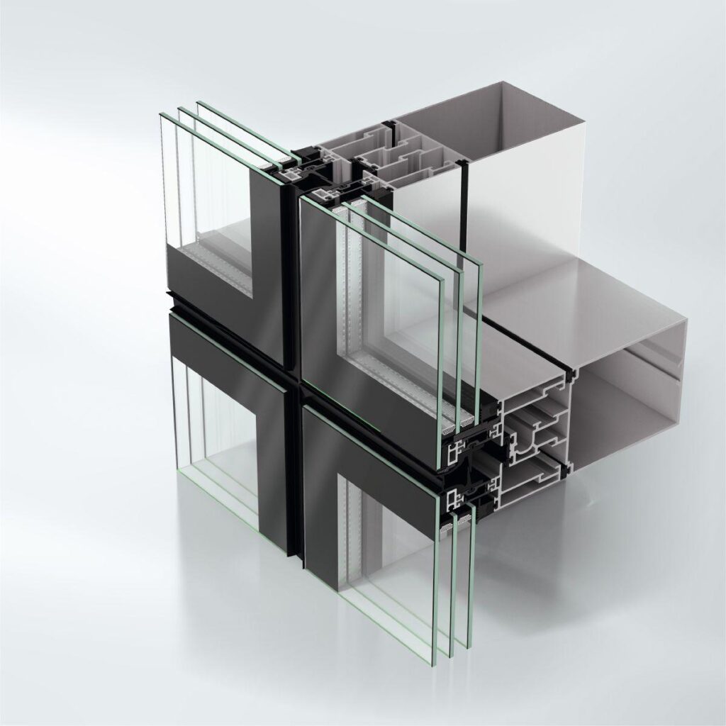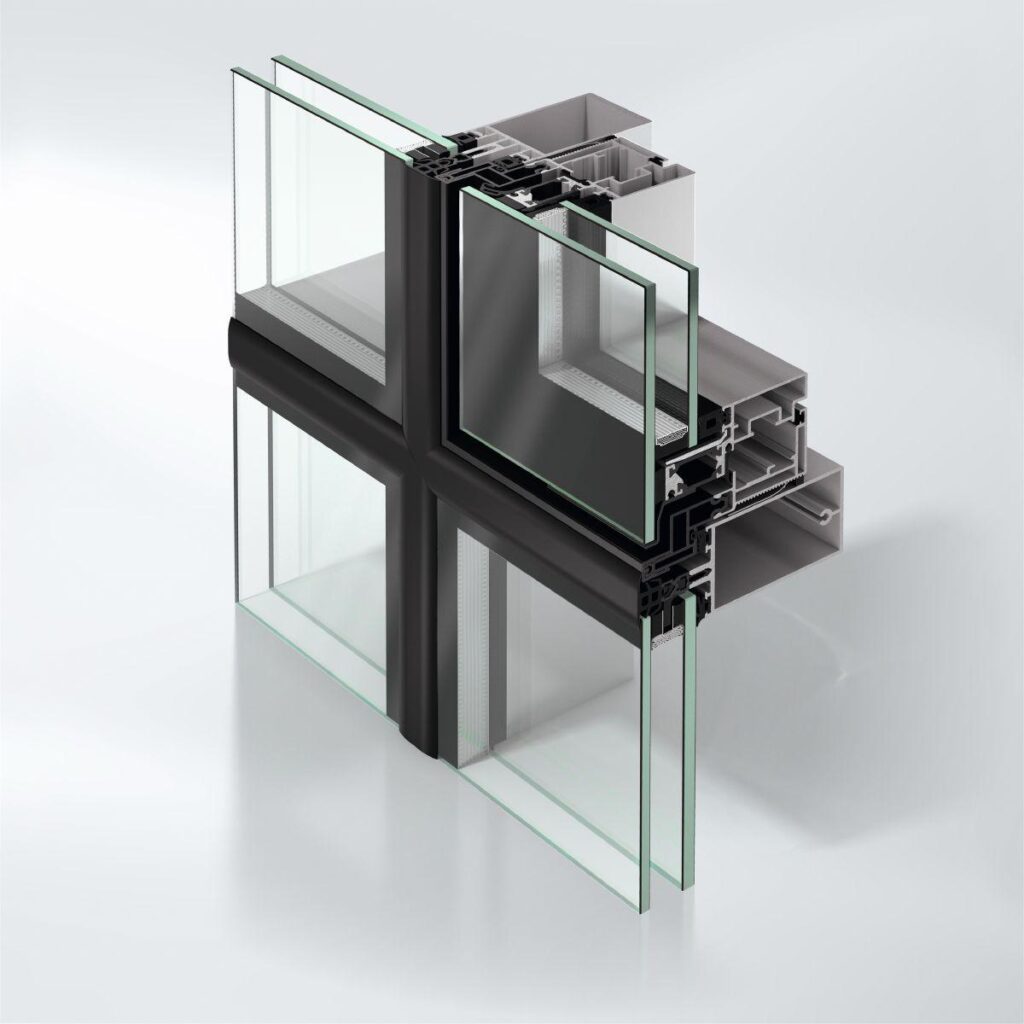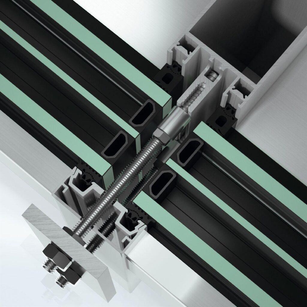
Mullion/transom façade for a variety of solutions with high thermal insulation
The highly thermally insulated Schüco FWS 50.HI (High Insulated) façade system offers high flexibility and attractive design options for highly thermally insulated façades and skylight areas in a narrow steel look, including optimised fabrication and installation processes. Thanks to a broad system range, solutions for the most varied requirements and applications can be implemented.
A transparent system solution integrated in the profile for spandrel safety barriers blends seamlessly and elegantly into the external façade appearance. The required safety barrier loading for floor-to-ceiling opening units and low spandrel heights can be implemented with consistent profile face widths and a continuous profile.
The mullion/transom façade offers a high level of design freedom with a large selection of pressure plates and façade cover caps, as well as the option of being combined with Schüco window, door and sliding systems.
System-optimised components guarantee the simple and reliable integration of electrical components, e.g. for automated Schüco door or sun shading installations.
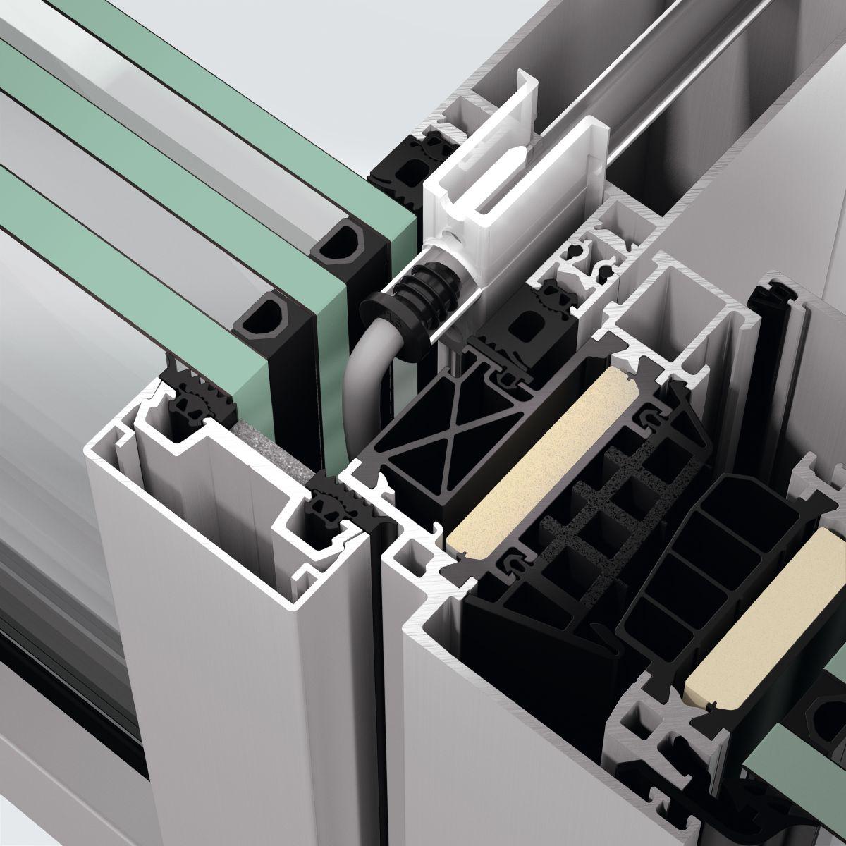
Schüco FWS 50.SI/HI glass/aluminium non-ventilated façade with integrated CTB solar shading
As a mullion/transom construction, with concealed external Schüco CTB solar shading integrated in front of the intermediate floor behind opaque cladding (ProSol TF PV modules), for multi-storey façades.
Design features:
Façade construction with an aluminium pressure plate and foam strip with an inwardly highly reflective aluminium foil to prevent thermal radiation.
Vertical glass pressure plates with a solar shading guide groove must be used.
Load-bearing structure:
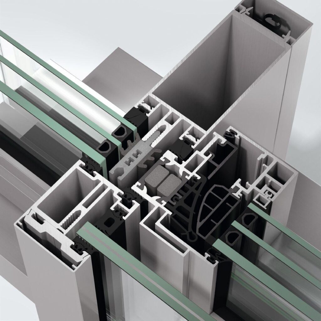
The load-bearing structure of the façade construction consists of rectangular multi-chamber hollow profiles with an inner face width of 50 mm and, when using CTB, with an outer face width of 85 mm in the area of the mullion. The load-bearing profiles are located on the room side. All profile edges are rounded.
The façade units are mounted as ribbon façades between the panel levels.
The forces from the mullion/transom construction are transferred to the load-bearing building structure via special façade fixing brackets.
The insulating panel (CTB box) is fixed in place on the brackets using appropriate fixings.
A long connector adapter profile is inserted in the mullion profiles and screwed to the aforementioned installation brackets.
All horizontal joints must be constructed using the joint connectors and joint tolerance seals belonging to the system.
Gasket principle:
The fields of the load-bearing structure are fitted with rebate gaskets in several levels.
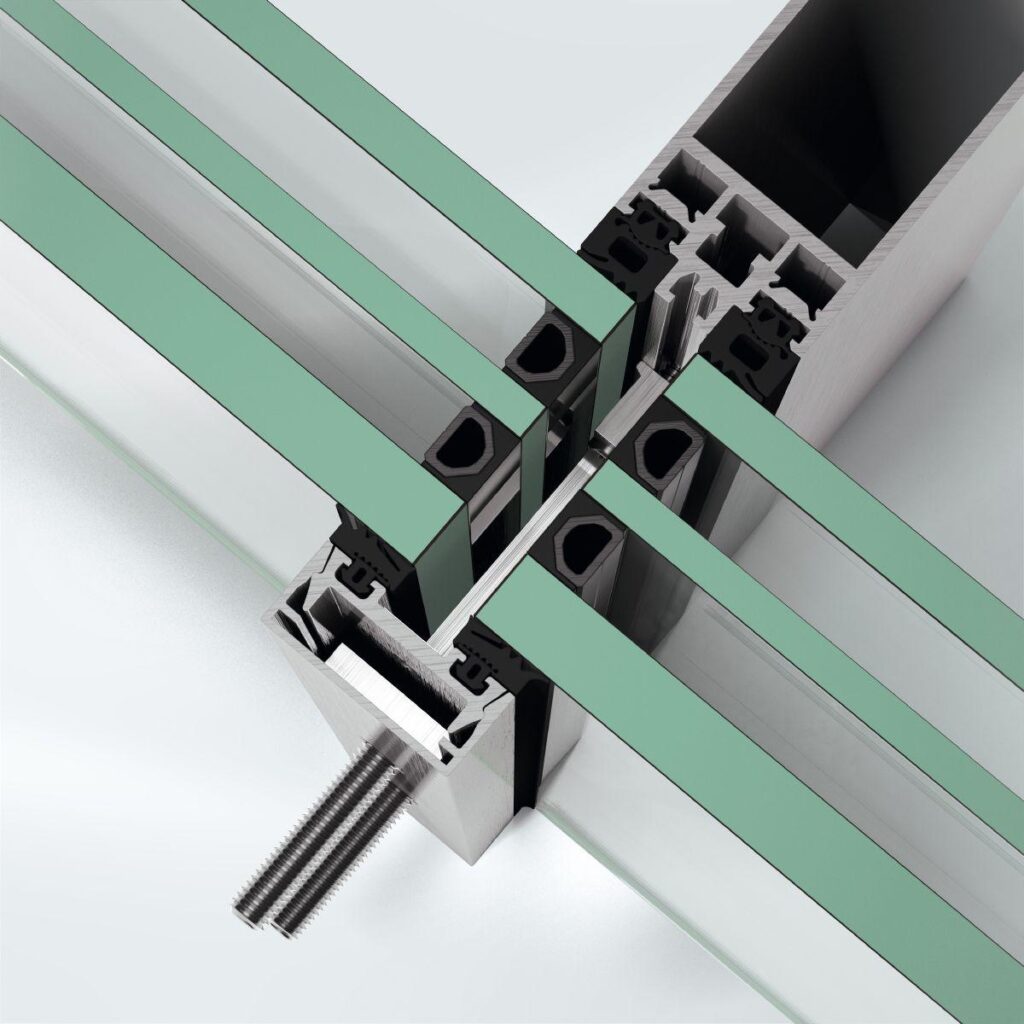
The area where the transoms and mullions overlap is sealed by the fold-out rebate gasket; the gasket leg is notched, allowing the gasket to be inserted in the joint area. In order to guarantee that no tension builds up in the transoms, joint tolerance pads and punched slots are used in the overlap area of the transom and mullion profiles.
The area where the mullion and horizontal transom profile on level 4 overlap is sealed by means of a liquid sealant, which is applied in openings in the area where the mullion and horizontal transom profile overlap. Pre-filler is first inserted in the outer hollow chambers of the horizontal transom profile for a defined distribution of the liquid sealant. In order to guarantee that no tension builds up in the horizontal transom profiles on level 4, joint tolerance pads and punched slots are used in the horizontal transom profile.
The insulating panel is sealed towards the inside by means of continuous gaskets, which are inserted in the longitudinal grooves of the panels and in the isolators of the horizontal transom profiles, and which are sealed using liquid sealant. The bottom gasket joint must be sealed using butyl tape. The top gasket joint is sealed by means of a joint seal to be filled with liquid sealant. The panel joint is sealed using gasket corners, which are inserted in the side grooves of the panel and bonded together. On the outside of the panel, a joint plate with butyl tape applied to it is also screwed onto the panel joint.
Glazing:
All glazing, even in the insert units, lies in the same plane.
The vertical pressure plates have side guide grooves and rubbing strips where the louvre blades of the Schüco CTB solar shading are guided. In accordance with DIBt guidelines, the clamping connection between the pressure plates and the load-bearing structure must be designed in accordance with the conditions of the existing general building authority approval Z-147.4.452 and/or the general building authority test certificates dated 02/2009.
The glazing gaskets made from weather-resistant, black EPDM on the room side are of different depths in the mullions and transoms (6 mm offset).
Two individual gaskets made from weather-resistant, black EPDM, with a height of 5 mm, are positioned on the outside. Cruciform gaskets made from EPDM must be used where mullions and transoms join.
Ventilation:
Rebate base ventilation and vapour pressure equalisation take place at all four corners of each module field into the mullion rebate.
For field drainage and ventilation, appropriate openings must be made in the aluminium pressure plates, cover caps and gaskets.
Integration of CTB:
The Schüco CTB solar shading is concealed in an installation space in front of the intermediate floor of the façade construction. To achieve this, a thermal insulation panel is positioned in the area of the façade load-bearing structure between two floors, which defines the installation space for the solar shading and represents the thermal insulation level. The thermal insulation panel is colour-coated. After installing the solar shading, a cover plate is inserted and fixed in two U-shaped profiles, which are attached to the panel strip.
A ventilated spandrel (between the ground and first floor, made from ProSol TF photovoltaic modules, otherwise as a sheet metal façade), which is fixed to the load-bearing structure by means of brackets with appropriate attachments, forms the outer seal of the solar shading installation space.
Attachments to the building structure:
Attachments to the building structure are on the same drainage level. The vulcanised gasket leg of the vapour barriers for this design is pushed into these attachment profiles to guarantee a weathertight façade attachment without additional mechanical fixings. The vapour barriers are inserted all round, in the same drainage plane behind the drainage system of the façade structure.
All fixing screws for external use must be stainless steel A4, those in concealed areas must be stainless steel A2.
Profile face widths inside:
Mullion, assembly mullion, transom: 50 mm
Profile basic depths:
See attached construction suggestions
The technical dimensions, face widths and depths illustrated are minimum requirements and must be adapted to the structural requirements and any planning documentation of the client.
Any adjustments must be incorporated into the price of the respective item and the client must be informed when the tender is submitted.
Tell us what you need and we’ll get back to you with a custom offer.
Përshkruani shkurt projektin tuaj. Do t’ju kontaktojmë së shpejti.